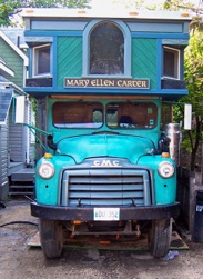
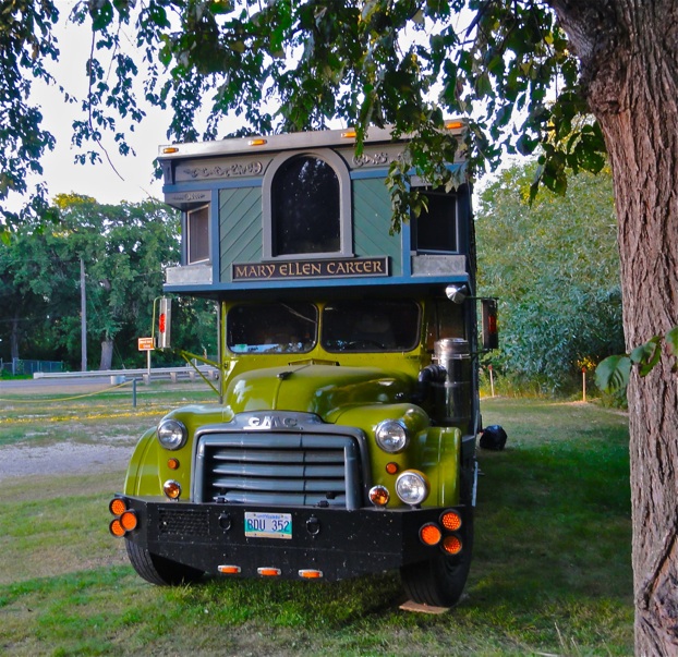
Part 2 - Miss Mary’s New Engine

Up till now Miss Mary’s 6 cylinder had been doing a job that her original engineers would have deemed miraculous. I know her huge range of gear combinations is a contributing factor to her longevity, but the fact is I am taxing the poor engine to near failure. It has done so much more than I ever considered whenI started down this long road and have decided it is time for more power. Our Band - Still Standing has been getting more and more work abroad and if we wanted to be able to travel far and wide we were going to need more power to be able to sustain a reasonable highway speed and maybe even tow a car.
There are no more big gasoline sixes out there and there is not a diesel that will work right with her gearing. And don’t kid yourself - nothing about a diesel is cheap, not even the fuel anymore. I have done some work with 5.9 Cummiins 12 valve engines, but this engine makes its power in all the wrong ways for Miss Mary’e gearing. Contrary to popular belief a diesel working hard as it would be here would be hard pressed to to better than 8-9 mpg on a good day. The engine in her now gets maybe 3-4 MPG running on propane. Calculate the significant fuel savings burning propane and that equivalent fuel cost narrows the operating cost even closer.
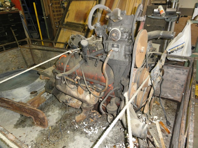
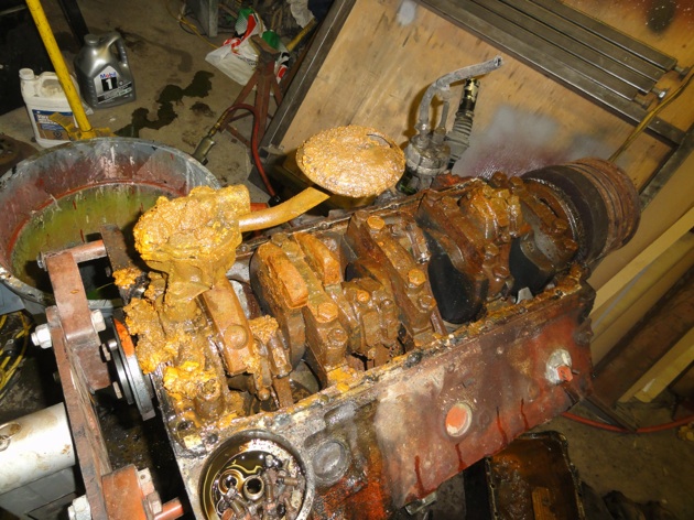
I was going to go with a big V8 - an engine configuration I am not fond of but have no choice. I decided to look for a GMC 427 tall deck truck engine. These differ from a car engine in that they have a heavier crankshaft, 4 bolt main bearings and 4 ring pistons to handle heavier loads. I discovered they can be hard to find as drag racers have been scooping them up to convert to stroker engines. Every clown I found seemed to think it was his retirement fund and I was just looking for a used core to rebuild. It took about a year but I finally found one for the reasonable sum of $300.00. I pulled it out of this crusty old fellow. There was one hitch - it was seized and the owner did not know why as it had been driven to his yard in the last few years. When I saw it - the air filter was missing...........

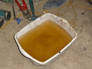
All that came out of the crankcase was water. Nearly 2 gallons of it I am sure. I began pulling the engine apart . It got ugly fast.


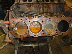
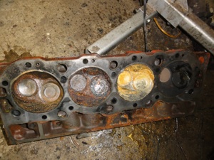
Well it had all the markings of a Mary Ellen Carter project for sure - nothing is ever easy. In the big picture though this is not all bad. All the valves and seats had to go anyway as they would need to be changed to Stellite to burn propane. 2 of the cylinders were too rusty to be saved so they have been sleeved and all bored .040 over. But I had anticipated a rebore no matter what.The crank is good. Two connecting rods, the cam, lifters, rocker arms, and valve spring are toast so they will be replaced.
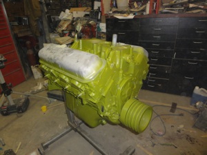
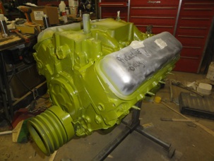
I have the engine back from the machine shop now and have given it a lick of paint to match the cab. The valve covers are even rusted out and so for now they are for decoration only. A crate engine would have been no more expensive in the end if I could have found one with these specifications. There will be a plethora of little custom fabrication jobs to do before this engine is finally nestled in Miss Mary’s engine bay. For now I must patiently wait for spring and hope I have the time and money to start as soon as spring comes. There will be a ridiculous amount of fiddling to get her all dialed in, but I have great hopes Miss Mary will finally have the power she needs to make high speed cruising effortless!
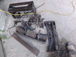
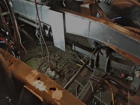
One of the things I have thought would be a good idea for a long time for Miss Mary or any vehicle with a loft is to box the frame from behind the point where the body stops and goes up for the loft to the front of the frame. Mary’s Structural box beam body distributes the load very evenly over the frame but it is logical there must be more loading where the body stops on the frame. Now would be the time to do this job with the engine and transmission out.To that end I began by pulling all the frame cross members to make way for the 1/4” plate I would be using to fill the inside of her “C” channel frame.This was a big job as most of them were riveted together and access was very tight. Many hours of work with a grinder, air chisel , plasma cutter and various types of cutoff tools. The pic on the right is the pile of stuff that came out.
I had a steel warehouse cut me 3 pieces of 1/4 “ steel plate 8 feet long and the depth of the inside of the existing frame rails. I made templates of MDF the shapes of the frame rails so had an accurate pattern to start cutting the steel. Again if I am making working with steel plate sound easy allow me to assure this is not a job for the uninitiated or under tooled. I got the frame rails boxed and continuously welded in a long day of careful fitting and stitch welding.
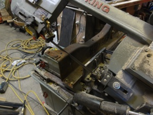
Now I had to reinstall the one cross member I was going to use. I started by cutting it down to the new frame rail spacing. I didn't want to weld it solid so settled for welding angle iron to the frame and then bolting the cut down cross member which I redrilled to accept the new brackets. It was a stupid amount of fiddling as I discovered the cross member was slightly rounded in almost every plane for some reason making squaring it up for cutting and fitting a challenge. Add to that the confined working space made this small job take several hours. The pic on the right is the old cross member finally installed!
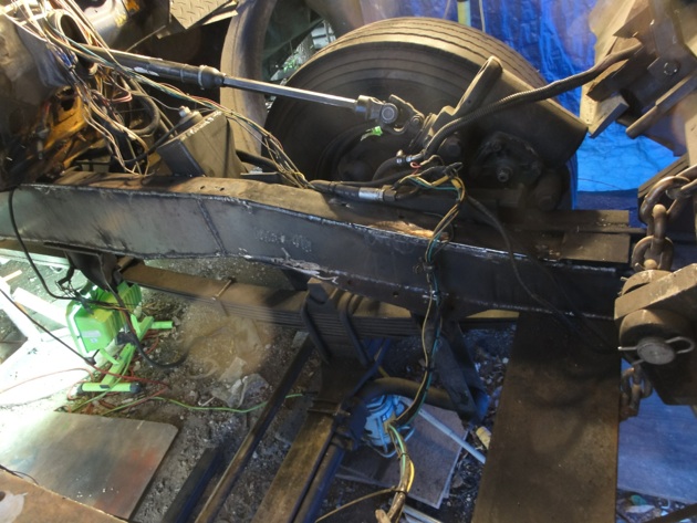
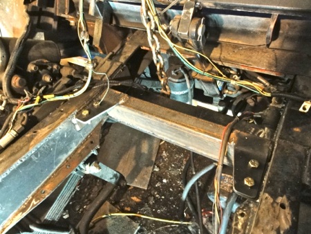
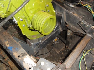
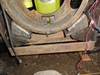
The photo below shows what will become the new rear cross member when the engine goes in. I have welded 5/8” by 8” steel plate to the frame with a couple sets of extra holes to give me some adjustability down if I need it. I will then again bolt on the factory style mounts and finish by connecting it all with heavy angle iron as I did before. The connection of the bell housing to the mounts will again involve new adaptor blocks that I will make on the fly as I fit the engine. I am determined to set the engine more level than it has ever been and cure a fluid level problem I have had with the transmission
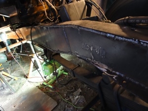
This is a new crossmember at the very front of the frame. It is a piece of 2” by 4” by 1/4”wall box tubing that is welded continuously to another piece of 5/8” plate that forms the mount I had to make for the modern front suspension. The crossmember becomes a bolted member similar to the original mounts which were riveted but overall much stronger..
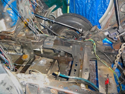
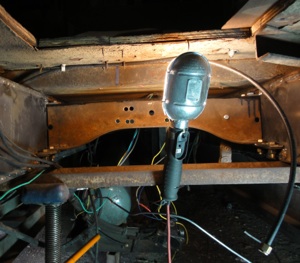
This is a pic of the new hydraulic brake booster I am very excited about.I salvaged this and the pedal assembly of a current GMC school bus. I have been experimenting for years with different combinations of master cylinders and HydroVac vacuum boosters with nothing ever giving me exactly what I wanted. Plus the added disadvantage of only one brake line for everything. Blow a flex hose you lose all your brakes.! This will give me a split master cylinder with at least half the brakes if one line fails
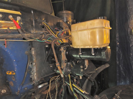
This system also has a very cool electric motor back up should the hydraulic system fail due to engine stall etc. I also at this time moved the steering column ,pedals and drivers seat 5” inches closer to the side to correct a factory offset that has always wasted a lot of space in the cab.I had to remove and install a large piece of the firewall with heavier gauge steel plate to support the weight of the unit
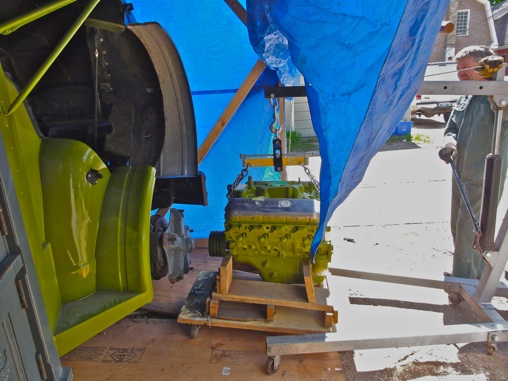
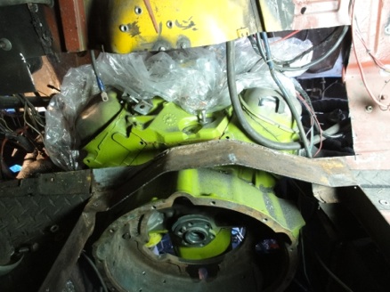
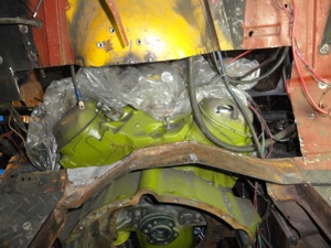
Finally comes the day to begin the new engine installation! It was a very awkward fit having to come in from the side over the frame. Ranger Dan ( Too Slim ) Laramee was in town for a few days and lent a valuable hand to get Miss Marys new engine in!
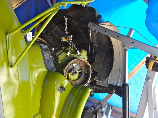
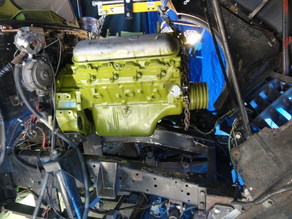
Once we had the engine where we wanted it, ( which took a ridiculously long time due to considerations for transmission clearance, starter clearance, firewall clearance etc) , then came the job of fabricating custom engine cross members to attach the engine mounts to. I did not pay attention to what the frame of the truck I got the engine from looked like, but when I was done this is what I wound up with . And then what it looked like installed below.
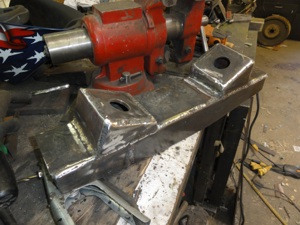


Once again I used my reverse engineering technique of mounting the pieces of steel plate that had to be there,like the ones that bolted to the bell housing and motor mounts, and then made wooden templates to represent the odd triangles that would be needed to connect them before I cut them from plate and welded them in place.
Looking like a tear in the space/time continuum , this is the hole it would take to get the clearance around the back of the new engine.
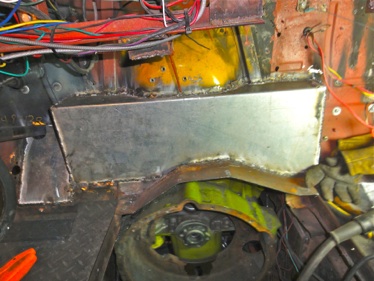
I decided I would have to give up the appearance of symmetry in more than one area as I adapted the new engine as the original was offset to provide clearance for the original master cylinder ( which was under the floor) as well as the original pedal linkage. Here is the hole covered with some 16 gauge sheet metal I bent up on my brake and stitch welded into place
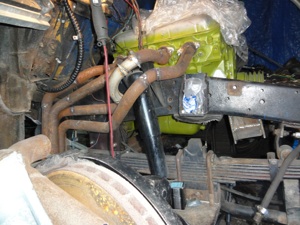
Next on my hit list was the exhaust system. This was going to be a huge headache as I had less than an inch of clearance between the cylinder head and the frame. There was NO exhaust system made by ANYONE that was going to fit in there! It would have to be yet another custom fabrication.
I started by cutting the collectors off a used set of headers I had bought and clamping them in place 90 degrees off their original plane. Then I took the tubes and cut them about 1/2” from the flanges and bolted them to the cylinder head. From here I went and bought another set of used headers and cut them up as well so I had a selection of curved pieces to pick from.
The tubes would have to go over the frame and wrap around my homemade shock towers as well as anything else that got in the way. I tacked the pieces as I went then removed them when I was done so I could continuously stitch weld them together.
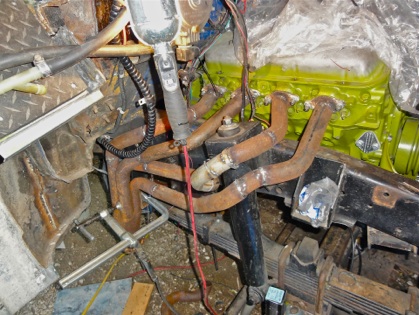
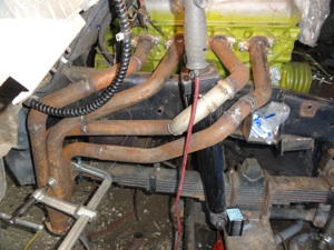
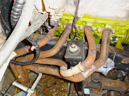

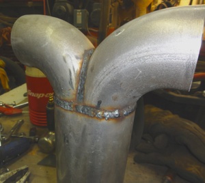
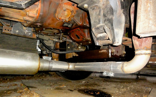
I used 3’’ pipe for the collectors and made a custom union to 4” to go the rest of the way to the back of the bus. I used a type of clamp that does not crush the pipe to make all the connections in case I ever have to remove the transmission for service This turned out very nicely.
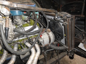
Another nightmare was the cooling system! There was not going to be anywhere near enough cooling with the radiator I had been using and the one that went with the big V8 was simply too massive to fit under the hood. I found a new 2 core/1 inch tube universal aluminum radiator a radiator guy figured should cool it, but even it would be a tight fit. I made the custom framework you see here and mounted 2 electric fans as there was not going to be anyway to use the stock fan
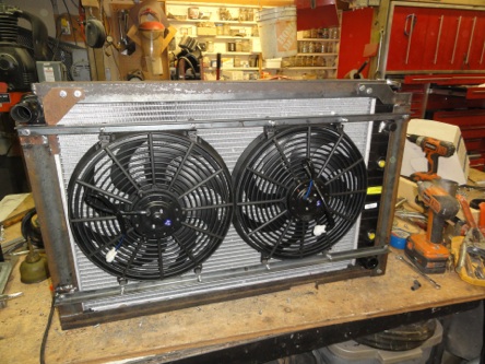
as the steering box blocked me on the drivers side from centering the assembly in the frame. I also wound up dropping it about 3/4’ on the passengers side as well as tilting it back to clear the hood as it closed.

Now from this point on I found myself in a serious time crunch as we needed Miss Mary for the start of the summer touring season and so I wound up taking time off work as well as abusing two of my best friends as we worked frantically to meet our July 1st debut at Countryfest in Dauphin Manitoba some 300 miles away. We did an amazing amount of work in the next 7 days as the new wiring and ignition got sorted out.I simply did not have the time to take pictures! Our tech guru Greg worked with me for nearly a week, even taking time off work .Ranger Dan and I finished about 11 PM on the friday and we left the next day breaking in the engine as we went. It was amazing and worked better the more I drove her. So far she delivers more top speed with about 40% better fuel economy. There will be much dialing in of the fuel system in the days ahead and the propane part of the system is no longer adequate for the bigger engine. But Ranger dan brought a bigger one in with him from Calgary so I will try that in the days to come as well as tweaking the gasoline part of the fuel system.
This is where the project is to date.All that is left to do to deem Miss Mary a finished project is to finally update the rear suspension and finish the driving cab interior once and for all! Keep Watching!
Paul


P.S. If you like this type of vehicle check out Mr. Sharkeys webpage! He has collection of converted trucks, buses and trailers sure to please - http://www.mrsharkey.com/